Nuclear Reactor
The nuclear reactor is the heart of the Basal’s power generation system. It provides the energy needed to propel the ship, power its systems, and support the crew’s needs. The Meridian Basal employs the TIR-350 (Tri-Loop Integral Reactor, 350MWth) nuclear reactor. It is an integral pressurized water reactor (iPWR) design, which is compact and efficient, making it suitable for use on a submersible.
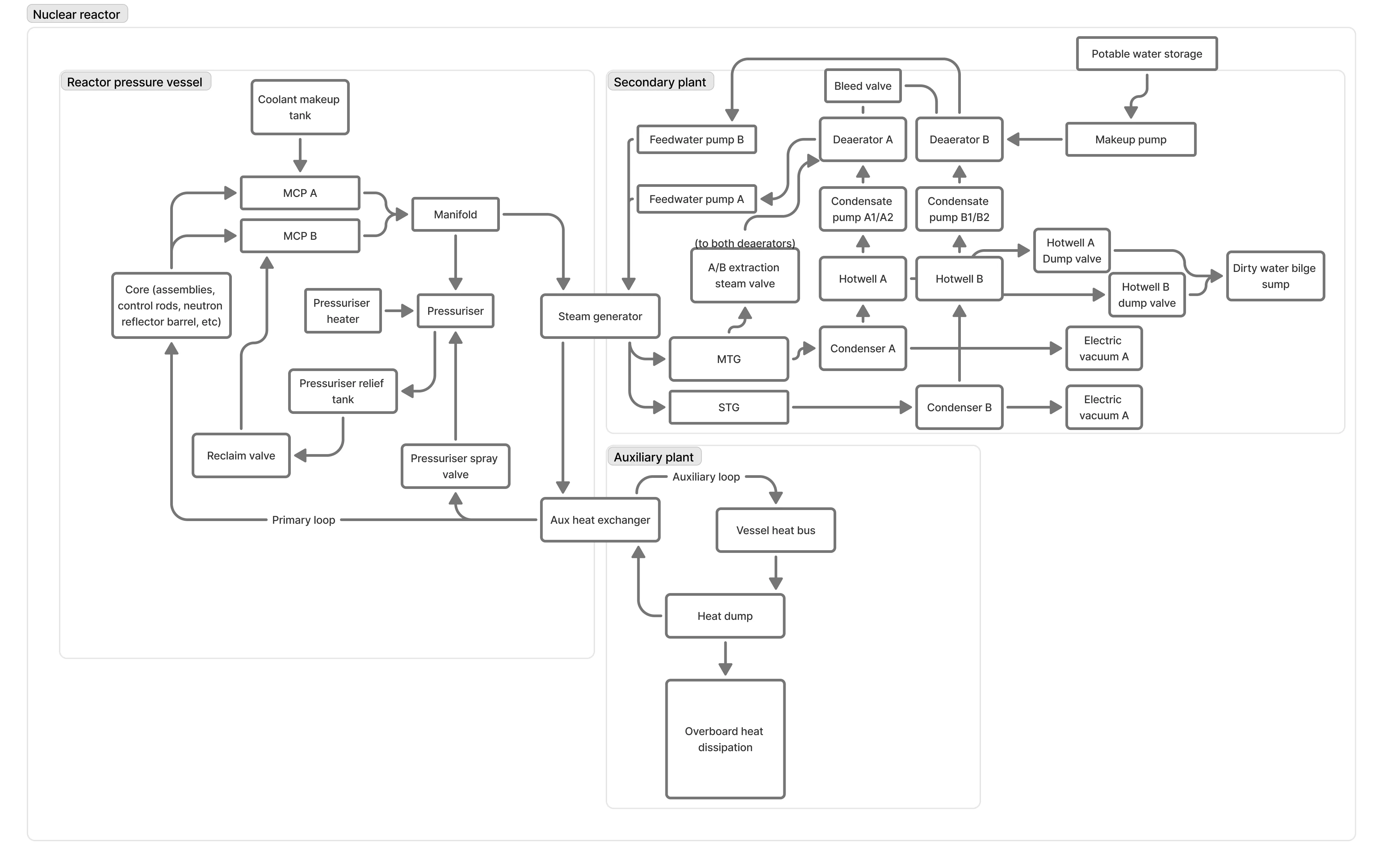
The tri-loop design consists of three separate coolant loops: the primary loop, the secondary loop, and the auxiliary loop. The primary loop circulates coolant through the reactor core to absorb the heat generated by nuclear fission. The secondary loop uses the heat from the primary loop to generate steam that powers the ship’s turbines and generates electricity. The auxiliary loop is used for various support functions, such as providing heat to systems such as water treatment and HVAC.
The secondary plant loop employs two turbines. The main turbine (MTG) is a high-pressure turbine that generates the majority of the ship’s propulsion power. The secondary turbine (STG) is a low-pressure turbine that generates additional power for the ship’s systems and can also be used to provide backup power in case of a failure in the main turbine.
Plant Rating
Section titled “Plant Rating”The TIR-350 reactor has a maximum thermal output of 350 megawatts (MWth). This maximum should never be reached under normal operation, as the reactor is designed to operate at a lower power level to ensure safety and longevity. The reactor is typically operated at around 250-300 MWth, which provides sufficient power for the ship’s needs while also allowing for a margin of safety.
The MTG is rated to generate around 60-70 megawatts of electrical power (MWe) at its maximum output, while the STG is rated to generate around 20-30 MWe.
The electrical systems of the ship are designed to take in power from the turbines at any frequency, allowing the turbines to operate at their optimal speed regardless of the ship’s speed or load. This means that the turbines can operate at their maximum efficiency, providing the necessary power for propulsion and other systems without being limited by the ship’s speed or load. The electrical systems will then convert the variable frequency power from the turbines into the appropriate voltage and frequency (50Hz) for the ship’s systems, ensuring that all systems receive the power they need to operate effectively.
Primary Plant
Section titled “Primary Plant”As is common of an iPWR, the primary plant is a pressure vessel that contains the reactor core and the primary coolant. The reactor core consists of fuel assemblies and control rods. The fuel assemblies contain the nuclear fuel, which is typically enriched uranium or plutonium. The control rods are made out of hafnium, some with boron carbide inserts, and are used to control the rate of the nuclear reaction. By inserting the control rods into the reactor core, the crew can slow down or speed up the nuclear reaction, thus controlling the amount of heat generated. The primary coolant is typically water, which is circulated through the reactor core to absorb the heat generated by the nuclear reaction. The heated coolant then flows to the steam generator, where it transfers its heat to the secondary loop.
The primary plant is not nearly as complex as a land-based nuclear power plant. It is one large loop, but employs two main circulation pumps (MCP) to ensure that the coolant flows through the reactor core at the necessary rate. The MCPs pull coolant from the core and send it to the steam generator. The steam generator transfers most of the heat from the primary loop to the secondary loop, but purposefully leaves a substantial amount of heat in the primary loop to ensure that the coolant remains at a high temperature. The coolant then moves to the auxiliary heat exchanger, where the rest of the heat is transferred to the auxiliary loop. The coolant then returns to the reactor core to repeat the cycle.
The auxiliary heat exchanger is rated to be able to transfer the full 350MWth maximum thermal output of the reactor so it can be dumped in the event of an emergency, but it is not used under normal operation. Normally, the auxiliary loop is used to provide heat to the ship’s systems, such as water treatment and HVAC, which helps to improve the overall efficiency of the power generation system. By using the heat from the primary loop to support these systems, the ship can reduce its reliance on electricity generated by the secondary loop, thus freeing up more power for propulsion and other critical systems.
The primary plant uses pressuriser unit to maintain the pressure of the primary coolant. The pressuriser is a tank within the pressure vessel that contains a mixture of water and steam. By controlling the amount of steam in the pressuriser, the crew can maintain the pressure of the primary coolant at the desired level. This is important because the primary coolant must be kept at a high pressure to prevent it from boiling, which could lead to a loss of coolant accident. The pressuriser is equipped with heaters and spray nozzles that can be used to adjust the pressure as needed. The pressuriser is also connected to the primary coolant loop, allowing it to quickly respond to changes in the coolant temperature and pressure. The primary loop is a closed loop, therefore any coolant that exits the pressuriser via a relief valve is stored in a tank that can be used to replenish the primary coolant if needed.
Secondary plant
Section titled “Secondary plant”The secondary plant operates with two lines. The first line, called line A, is the main line that generates the majority of the ship’s propulsion power. The second line, called line B, is the service line that generates power for the sub’s crew and non-essential systems. Line A houses the MTG, and line B houses the STG.
Both lines move steam from the steam generator to their respective turbines, where the steam expands and drives the turbine blades, generating mechanical energy. The output steam is sent to their respective condensers, where it is cooled and condensed back into water. The condensate is then pumped into a hotwell, which serves as a reservoir for the condensate. From the hotwell, the condensate is pumped into the respective deaerator, where any remaining dissolved gases are removed from the water. The deaerated water is heated by steam from an extraction valve in each turbine’s output line, then pumped back into the steam generator to repeat the cycle.
Both condenser has its own electric vacuum pump to maintain the necessary vacuum for efficient condensation. The condensers are cooled by product water from the ship’s water treatment system.
Although the secondary plant is a closed loop, it is not a sealed system. The secondary plant has a makeup water system that can add water to the secondary loop if needed. This is important because the secondary loop can lose water due to leaks or evaporation. The makeup water system gets its water from the ship’s product water storage in the water treatment system. The makeup water is treated to remove any impurities before being added to the secondary loop, ensuring that the water quality in the secondary loop remains high and does not cause damage to the turbines or other components.